How Does an Automatic Diaphragm Valve Control Industrial Fluids?
An Automatic Diaphragm Valve is used in industrial piping systems that require remote operation, reliable shut-off and reduced contact between the process medium and mechanical valve components. It is particularly suitable for chemical dosing, water treatment, corrosive-fluid transfer, wastewater processing and automated equipment.
The valve uses a flexible diaphragm to open or close the internal flow passage. Unlike conventional valve structures that expose a stem and packing to the medium, the diaphragm separates the fluid from the bonnet and actuator. This arrangement helps reduce external leakage paths and protects upper mechanical components from corrosive substances.
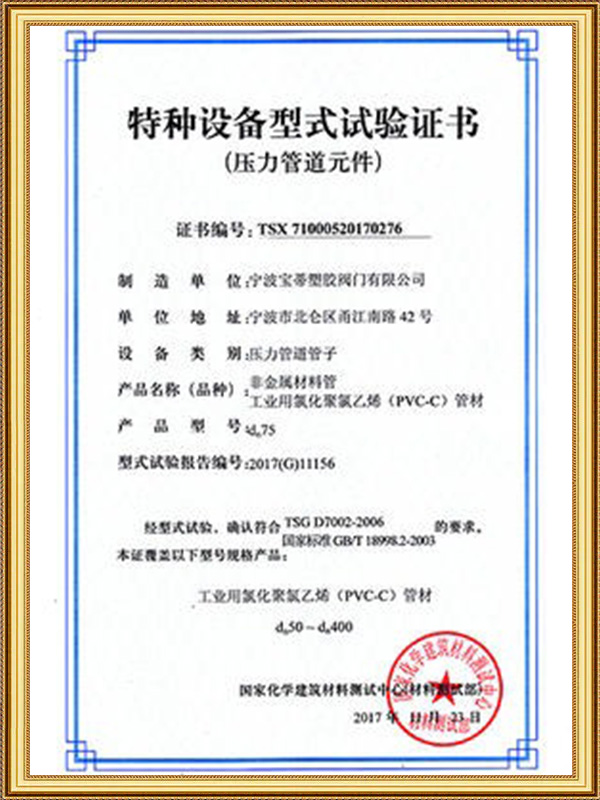
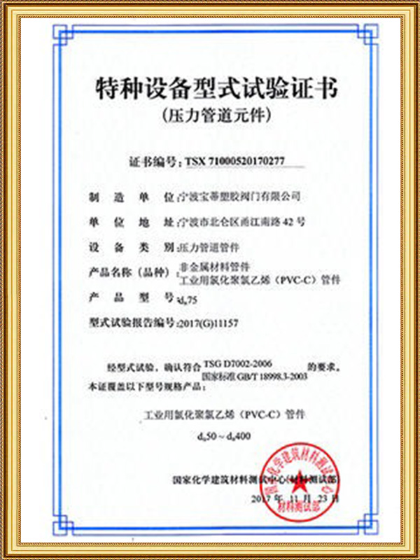
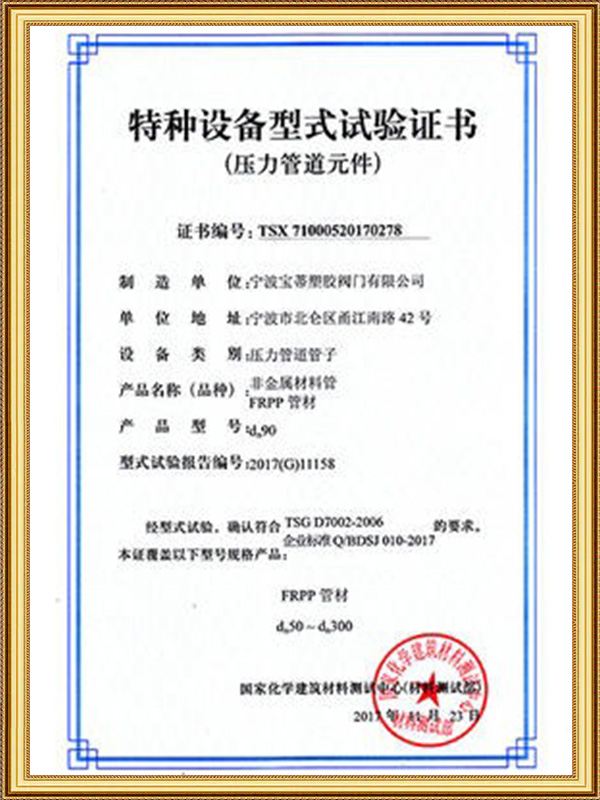
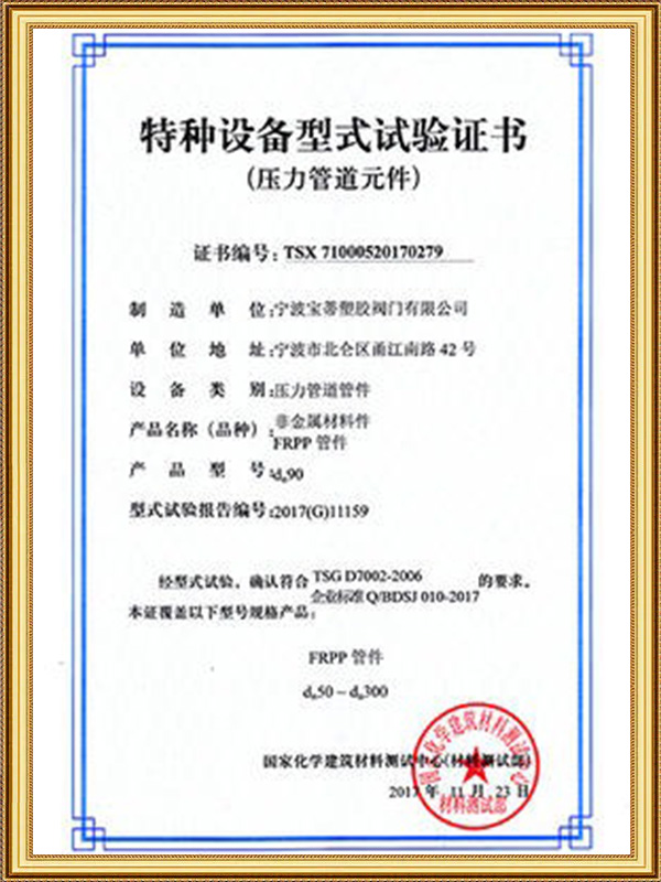
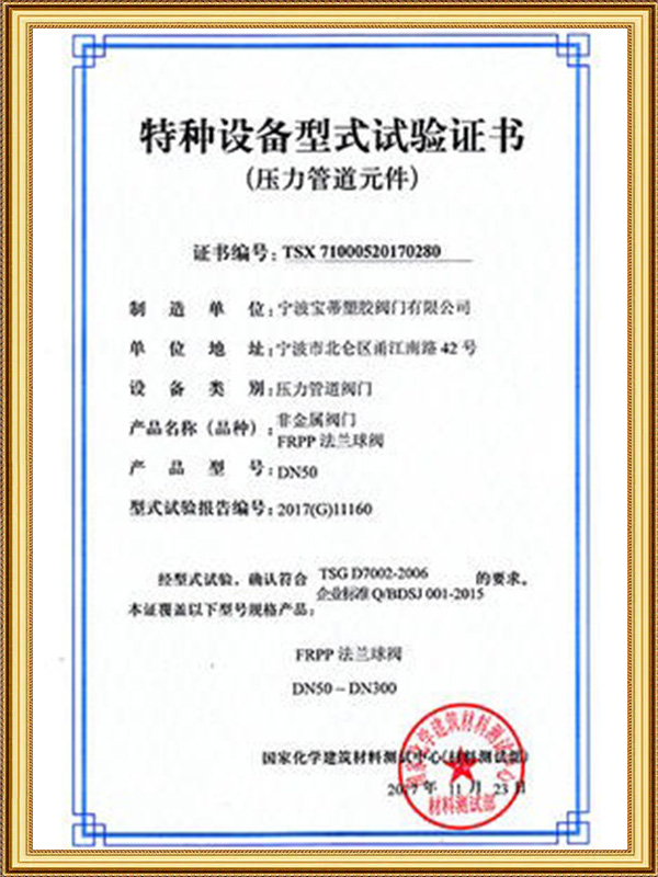
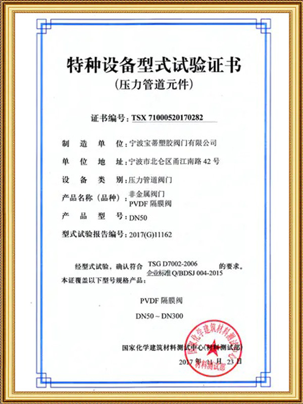
Ningbo Baodi Plastic Valve Co., Ltd. has been involved in industrial plastic valve production since 1979. Its first plastic diaphragm valve was manufactured in the same year and passed the technical appraisal of the Ministry of Chemical Industry in 1983. This experience provides a practical foundation for designing Automatic Diaphragm Valve products for demanding industrial piping systems.
What Is an Automatic Diaphragm Valve?
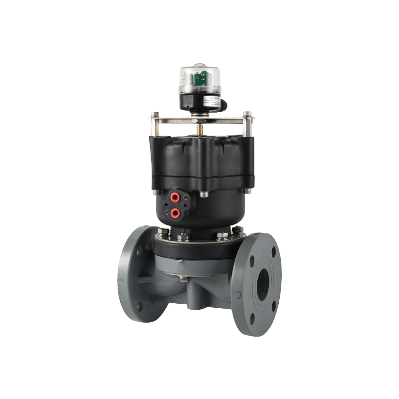
An Automatic Diaphragm Valve is a linear-motion valve consisting of a valve body, diaphragm, compressor, bonnet and automatic actuator. The actuator may use compressed air, electricity or hydraulic pressure to move the diaphragm.
When the compressor lifts, the diaphragm moves away from the valve-body sealing area and allows fluid to pass. When the compressor moves downward, the diaphragm is pressed against the sealing surface and stops the flow.
Fluid isolation: The diaphragm prevents the process medium from entering the actuator and upper stem area.
Shut-off function: The diaphragm forms the main seal between the upstream and downstream passages.
Automatic operation: The valve can respond to control-system commands without requiring direct manual operation.
Process integration: The Automatic Diaphragm Valve can be connected to level, pressure, flow, conductivity or chemical-control instruments.
Ningbo Baodi Plastic Valve Co., Ltd. is a principal drafter of the national standard for plastic diaphragm valves and the relevant chemical industry standard. This standardization experience is important because diaphragm travel, valve-body dimensions and pressure performance must remain consistent in industrial applications.
How Does an Automatic Diaphragm Valve Work?
Opening Process
The valve begins to open when the actuator receives an electrical or pneumatic signal. In a pneumatic design, compressed air acts on a piston or actuator diaphragm. In an electric design, a motor and transmission mechanism produce linear movement.
The actuator lifts the compressor, allowing the flexible diaphragm to move away from the sealing surface. As the diaphragm rises, the available flow area increases.
An on-off Automatic Diaphragm Valve normally moves directly to the fully open position. A modulating design can stop at intermediate positions to control flow, pressure or liquid level.
Closing Process
During closing, the actuator moves the compressor toward the valve body. The compressor distributes force across the diaphragm and presses it against the valve-body sealing area.
The actuator must produce enough thrust to overcome process pressure, differential pressure, diaphragm stiffness and fluid resistance. If the actuator force is too low, the valve may not close completely. If the force is excessive, the diaphragm may be over-compressed and damaged.
Ningbo Baodi Plastic Valve Co., Ltd. has more than four decades of experience manufacturing industrial plastic valves. Accurate control of the relationship between the valve body, diaphragm and compressor is essential for obtaining reliable sealing without unnecessary diaphragm stress.
Importance of Diaphragm Travel
Insufficient travel can prevent full opening and increase pressure loss. Excessive closing travel can cause permanent diaphragm deformation, cracking or separation between a chemical-resistant face and its flexible backing.
The actuator stroke should therefore be adjusted to provide full flow and reliable shut-off without applying excessive compression.
Main Components of an Automatic Diaphragm Valve
Valve Body
The valve body forms the fluid passage and provides the sealing surface for the diaphragm. Its internal shape influences flow resistance, drainage, cleaning and the ability to handle particles.
Industrial thermoplastic valve bodies may be manufactured from PVC, CPVC, PP or PVDF. Ningbo Baodi Plastic Valve Co., Ltd. expanded its product range to industrial plastic pipes and fittings in 2006, allowing valves and connected piping to be selected according to compatible materials and dimensions.
Diaphragm
The diaphragm is both a moving component and a sealing element. It bends during every operating cycle and remains in direct contact with the process medium.
A suitable diaphragm must provide chemical resistance, flexibility, mechanical strength and dimensional stability. It must also retain these properties throughout the required pressure and temperature range.
Compressor
The compressor transfers actuator force to the diaphragm. Its shape should distribute the load evenly over the sealing area.
Uneven compression may cause local fatigue, incomplete sealing or premature diaphragm failure.
Bonnet
The bonnet supports the compressor, guide mechanism and actuator connection. Under normal conditions, the diaphragm prevents the process fluid from entering the bonnet.
Leakage around the bonnet may indicate diaphragm damage and should be investigated promptly.
Actuator
The actuator generates the force required to open and close the valve. Its size depends on valve diameter, process pressure, maximum differential pressure and diaphragm stiffness.
Common accessories include solenoid valves, positioners, limit switches, air filter regulators and valve-position feedback devices.
Weir-Type and Straight-Through Automatic Diaphragm Valve
Weir-Type Design
A weir-type Automatic Diaphragm Valve has a raised sealing section inside the body. The diaphragm needs only a relatively short movement to contact the weir and stop the flow.
This design reduces diaphragm flexing and is commonly used for clean liquids, chemicals, water-treatment fluids and dosing applications.
The raised weir creates a more restricted internal passage, so the design may be less suitable for large solids or fluids that produce heavy sediment.
Straight-Through Design
A straight-through valve has a more open internal passage. It can provide lower resistance and improved passage for selected slurry, viscous liquids and particle-containing fluids.
The diaphragm must travel farther to close the passage. Greater movement can increase diaphragm flexing and affect service life under frequent operation.
Structure Comparison
| Parameter |
Weir-Type Automatic Diaphragm Valve |
Straight-Through Automatic Diaphragm Valve |
| Internal structure |
Raised sealing weir |
More direct flow passage |
| Diaphragm travel |
Shorter |
Longer |
| Flow resistance |
Moderate |
Usually lower when fully open |
| Particle handling |
Suitable mainly for clean or lightly contaminated fluids |
More suitable for selected slurry and solids |
| Diaphragm flexing |
Relatively low |
Relatively high |
| Typical application |
Chemicals, water treatment and dosing |
Wastewater, slurry and viscous media |
The correct design should be selected according to flow resistance, particle size, drainage requirements, cleaning method and expected operating frequency.
Automatic Diaphragm Valve Actuation Methods
Pneumatic Actuator
A pneumatic actuator uses compressed air to move a piston or internal actuator diaphragm. It provides fast response and is suitable for frequent switching and process interlocks.
The air supply should be clean, dry and maintained within the specified pressure range. Moisture and particles can affect solenoid valves, positioners and actuator seals.
Electric Actuator
An electric actuator uses a motor and gearing system to produce linear force. It is suitable where compressed air is unavailable or where the valve operates less frequently.
Electrical wiring, voltage, environmental protection and actuator speed must be checked before installation.
Hydraulic Actuator
A hydraulic actuator uses pressurized fluid to generate high thrust. It is normally selected for specialized applications requiring substantial operating force.
Actuator Comparison
| Parameter |
Pneumatic |
Electric |
Hydraulic |
| Power source |
Compressed air |
Electrical supply |
Hydraulic pressure |
| Operating speed |
Fast |
Moderate or slow |
Adjustable |
| Available force |
Moderate to high |
Depends on motor and gearing |
High |
| Fail-safe arrangement |
Practical with spring return |
May require backup power or spring system |
Requires dedicated hydraulic design |
| Typical use |
Frequent automated operation |
Remote control without plant air |
High-force special applications |
Normally Closed, Normally Open and Double-Acting Designs
Normally Closed
A normally closed Automatic Diaphragm Valve moves to the closed position when the control air or electrical power is removed.
This arrangement is often used in chemical dosing and hazardous-fluid pipelines where stopping the flow is the safer condition.
Normally Open
A normally open valve remains open when the control source is lost. It can be selected for cooling water, protective circulation or drainage systems where continuous flow is required for equipment safety.
Double Acting
A double-acting actuator uses external pressure for both opening and closing. When the supply fails, the valve may remain near its last position.
| Design |
Position After Utility Failure |
Typical Application |
| Normally closed |
Closed |
Chemical isolation and dosing |
| Normally open |
Open |
Cooling and emergency circulation |
| Double acting |
May remain in the last position |
Controlled industrial processes |
Ningbo Baodi Plastic Valve Co., Ltd. supplies thermoplastic valves to customers in more than 60 countries. Different operating environments demonstrate that the fail-safe position should be determined by process risk rather than by applying the same configuration to every pipeline.
On-Off and Modulating Control
On-Off Control
An on-off Automatic Diaphragm Valve moves between fully open and fully closed positions. It is commonly used for equipment isolation, batch transfer, tank filling, drainage and emergency shutdown.
The command may come from a push button, level switch, pressure switch, process controller or programmable control system.
Modulating Control
A modulating valve moves to intermediate positions according to a variable control signal. It can regulate flow, pressure, liquid level or chemical dosing rate.
A positioner compares the required valve position with the actual position and adjusts the actuator accordingly.
The relationship between diaphragm travel and flow is not always linear. Valve-body geometry, differential pressure and medium viscosity all influence the actual flow characteristic.
| Control Method |
Main Function |
| Digital on-off signal |
Full opening or closing |
| Pneumatic signal |
Direct pneumatic positioning |
| Analog current signal |
Proportional valve control |
| Digital communication |
Position control and diagnostic feedback |
Diaphragm Materials and Chemical Compatibility
EPDM
EPDM provides good flexibility and resistance to water and many diluted chemicals. It is commonly used in water treatment and selected acid or alkaline systems.
It is generally unsuitable for petroleum oils and many hydrocarbon fluids.
FKM
FKM provides resistance to many oils, fuels and chemicals. Its suitability should still be checked for strong alkalis, steam and specific reactive substances.
NBR
NBR offers good oil resistance and mechanical properties. It is used for air, oil and selected industrial fluids but has limited resistance to some oxidizing chemicals.
PTFE-Faced Diaphragm
A PTFE-faced diaphragm is suitable for many aggressive chemicals and high-purity fluids. A flexible backing supports the PTFE during repeated movement.
| Material |
Main Strength |
Typical Application |
Main Limitation |
| EPDM |
Water resistance and flexibility |
Water treatment and selected chemicals |
Normally unsuitable for oils |
| FKM |
Oil and chemical resistance |
Oil and selected chemical systems |
Not suitable for every alkaline medium |
| NBR |
Oil resistance and mechanical strength |
Air, oil and industrial fluids |
Limited oxidizing-chemical resistance |
| PTFE with backing |
Broad chemical resistance |
Corrosive and high-purity media |
Requires compatible backing and controlled travel |
Ningbo Baodi Plastic Valve Co., Ltd. has designed plastic valves for demanding industries for more than 40 years. Reliable operation requires compatibility between the valve body, diaphragm, seals and any other wetted components.
Valve Body Materials for an Automatic Diaphragm Valve
PVC
PVC is used for ambient-temperature water treatment and many general chemical applications. Its allowable pressure decreases as temperature rises.
CPVC
CPVC offers improved temperature capability compared with standard PVC. Ningbo Baodi Plastic Valve Co., Ltd. was one of the early domestic enterprises to apply CPVC to industrial-grade piping valves.
A CPVC Automatic Diaphragm Valve can be considered for selected hot-water and chemical pipelines when the diaphragm and seals are also compatible.
PP
PP is lightweight and resistant to many acids and alkaline fluids. Its pressure capability depends on temperature and material grade.
PVDF
PVDF is suitable for many aggressive chemicals and high-purity applications. The exact chemical concentration and temperature must still be confirmed.
Important Selection Parameters
Nominal Size and Flow Capacity
The valve size should be selected according to required flow and acceptable pressure loss. An oversized modulating valve may operate at a very small opening and provide poor control accuracy.
An undersized valve may create excessive velocity, noise and pressure loss.
Pressure and Temperature
The pressure rating must cover normal pressure, maximum pressure and possible surges. Thermoplastic valve pressure ratings normally decrease as temperature rises.
Maximum Differential Pressure
The actuator must be capable of opening or closing the valve under the maximum difference between upstream and downstream pressure.
A valve body may withstand the system pressure while an undersized actuator still fails to close the valve.
Actuator Supply Pressure
Low pneumatic supply pressure can cause slow movement or incomplete closure. Excessive pressure can increase component loads and diaphragm compression.
Cycle Frequency
Frequent operation increases diaphragm flexing. The expected number of cycles should be considered when selecting the diaphragm and actuator.
Fail-Safe Position
The required failure position may be closed, open or unchanged. The selection should be based on process safety, environmental risk and equipment protection.
Installation and Commissioning Guidelines
Inspect and Clean the System
Before installation, check the valve body, diaphragm, actuator and accessories. Remove sand, plastic fragments, welding residue and sealing material from the pipeline.
The valve should not be used to pull misaligned pipes into position. External stress can distort a thermoplastic body and affect diaphragm sealing.
Connect the Control Supply
Pneumatic systems should use clean and dry compressed air. Electric actuators should be connected according to the correct voltage, wiring and environmental protection requirements.
Confirm the Fail-Safe Position
After installation, remove the control signal or utility supply and check whether the Automatic Diaphragm Valve moves to the intended safety position.
Ningbo Baodi Plastic Valve Co., Ltd. has obtained ISO 9001, ISO 14001 and ISO 45001 system certifications. Manufacturing control supports stable valve quality, while commissioning is still necessary to verify the complete installed system.
Adjust Valve Travel
The opening and closing limits should be adjusted to provide full flow and reliable shut-off without over-compressing the diaphragm.
Limit switches and position feedback should be calibrated against the actual valve position.
Routine Maintenance and Common Problems
Diaphragm Inspection
The diaphragm should be checked for cracking, swelling, hardening, softening and permanent deformation. Leakage around the bonnet may indicate diaphragm failure.
Slow Operation
Slow response may result from low air pressure, blocked filters, small air tubing, insufficient solenoid-valve flow, actuator leakage or diaphragm hardening.
Incomplete Closing
Possible causes include particles on the sealing surface, inadequate actuator force, incorrect travel adjustment, body deformation or diaphragm damage.
Frequent Diaphragm Failure
Repeated failure may indicate chemical incompatibility, excessive temperature, over-compression, high cycle frequency or local flow erosion.
Ningbo Baodi Plastic Valve Co., Ltd. has served tens of thousands of industrial enterprises. In critical systems, preventive diaphragm replacement based on operating cycles and inspection history can reduce unexpected shutdowns.
Typical Applications of an Automatic Diaphragm Valve
Chemical Dosing
The valve can automatically control acids, alkalis and water-treatment chemicals while isolating the actuator from direct process contact.
Water and Wastewater Treatment
Automatic diaphragm valves are used in chemical addition, filtration, neutralization, sludge treatment and backwash systems.
Corrosive Fluid Transfer
Thermoplastic valve bodies combined with suitable diaphragms can control many corrosive fluids. Material selection should be based on concentration, temperature and pressure.
Slurry and Viscous Media
A straight-through Automatic Diaphragm Valve can be considered for selected slurry and viscous fluids after evaluating particle size, hardness and settling behavior.
Automated Equipment
The valve can be integrated into tanks, filters, mixing systems, dosing skids and process equipment for remote switching and safety interlocks.
Frequently Asked Questions About Automatic Diaphragm Valve
Does an Automatic Diaphragm Valve Need Compressed Air?
A pneumatic design requires compressed air. Electric and hydraulic designs use different power sources.
Can It Regulate Flow?
Yes. A modulating Automatic Diaphragm Valve equipped with a positioner can regulate flow, pressure or liquid level.
What Happens If the Air Supply Fails?
The valve may close, open or remain near its last position depending on the actuator configuration.
Can It Handle Slurry?
A straight-through design may handle selected slurry and particle-containing media. The particle size, concentration and abrasiveness must be evaluated.
Can the Diaphragm Be Replaced?
Most industrial diaphragm valves allow diaphragm replacement. The pipeline must be isolated, depressurized, drained and made safe before maintenance.
Why Does the Valve Leak After Closing?
Common causes include diaphragm damage, particles on the sealing surface, insufficient actuator force, incorrect travel or valve-body distortion.
How Often Should the Diaphragm Be Replaced?
The replacement interval depends on operating cycles, chemical compatibility, pressure, temperature and compression. Critical systems may use a planned replacement schedule.
Can a Plastic Automatic Diaphragm Valve Handle High Temperature?
It can operate within the limits of the body, diaphragm and seals. CPVC or PVDF may be suitable for selected applications above the normal range of PVC, but pressure-temperature derating must be confirmed.
What Information Is Needed Before Selection?
The required information includes process medium, chemical concentration, temperature, flow rate, operating pressure, maximum differential pressure, particle content, body material, diaphragm material, actuator type, control signal, operating speed, connection method and fail-safe position.

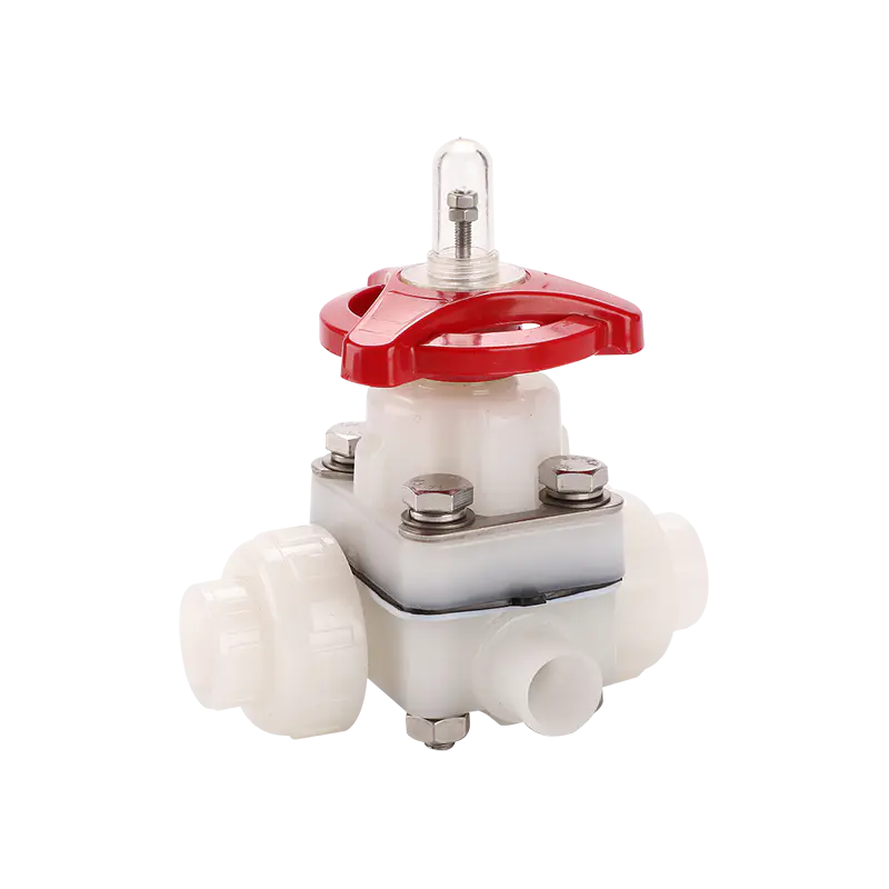

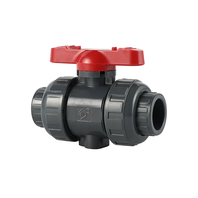
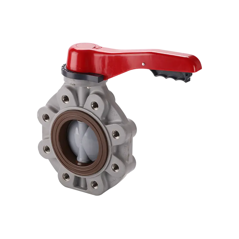
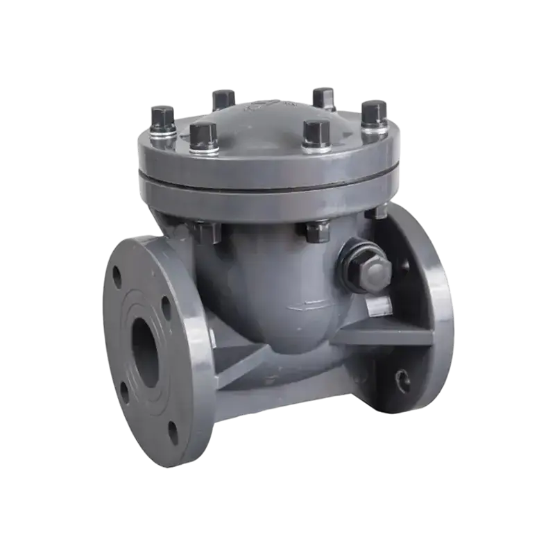
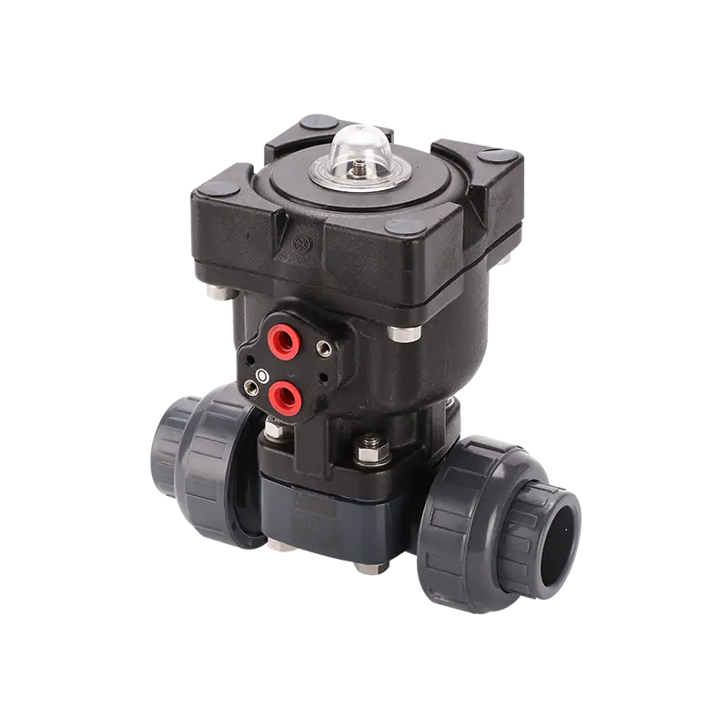
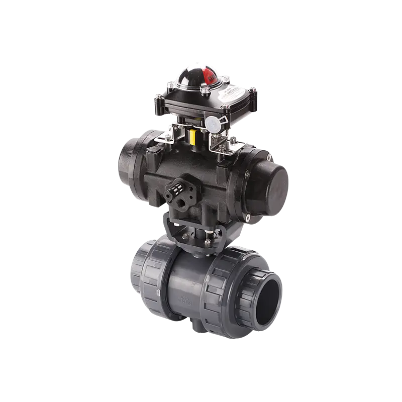
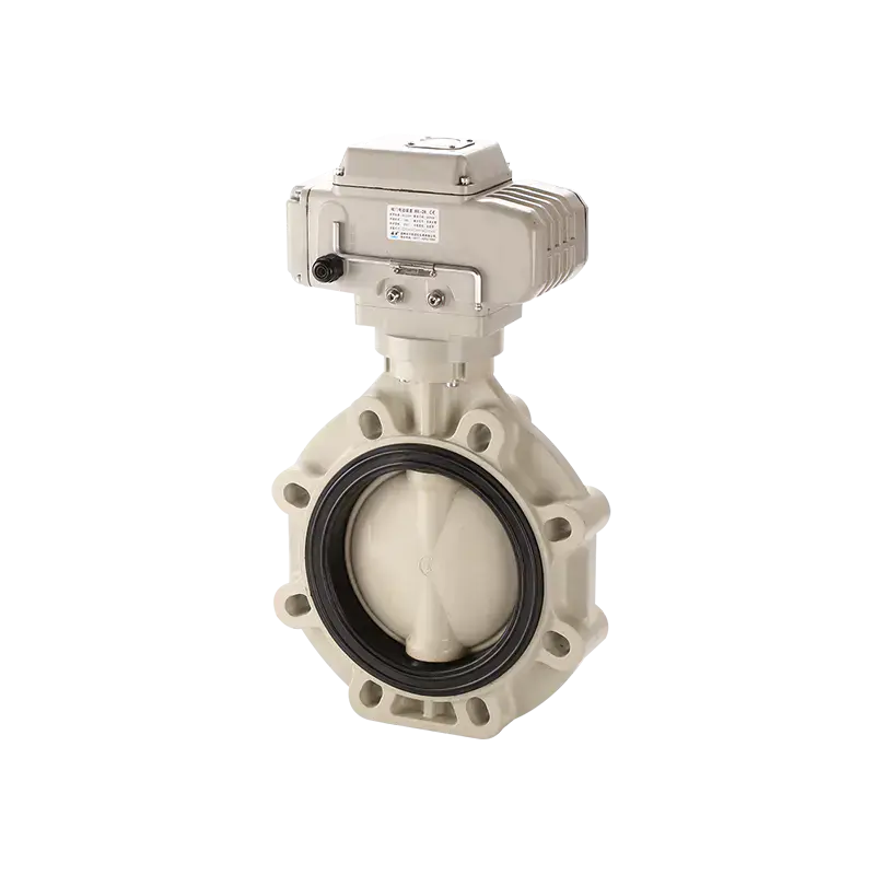
 উচ্চ চক্র জীবন, চমৎকার sealing কর্মক্ষমতা. হালকা ওজন এবং চমৎকার জারা প্রতিরোধী, যা অনন্য থার্মোপ্লাস্টিক নির্মাণের কারণে। ...
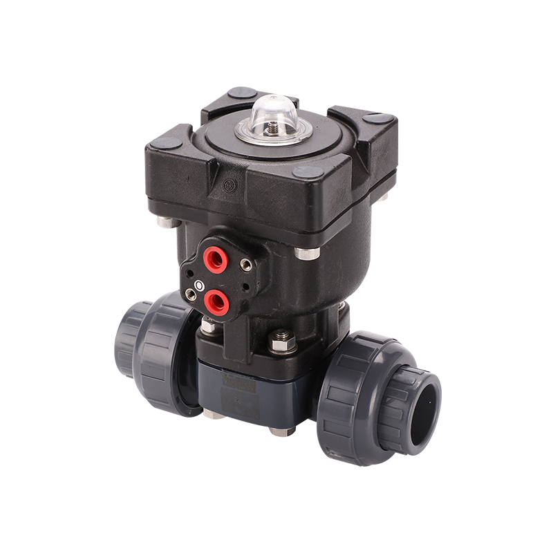 উচ্চ চক্র জীবন, চমৎকার sealing কর্মক্ষমতা. হালকা ওজন এবং চমৎকার জারা প্রতিরোধী, যা অনন্য থার্মোপ্লাস্টিক নির্মাণের কারণে। ...
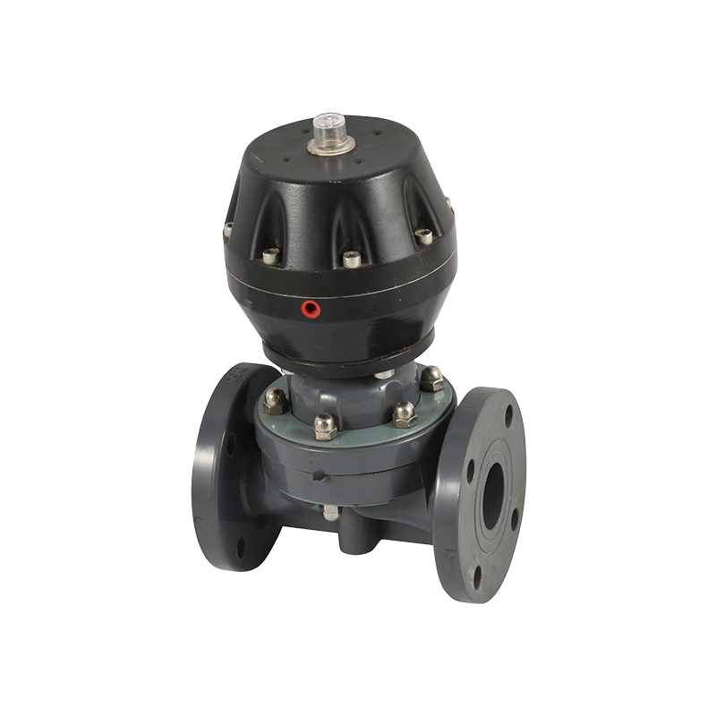 স্প্লিট স্ট্রাকচার, মেটাল অ্যাকচুয়েটর, সহজ রক্ষণাবেক্ষণ এবং ইনস্টলেশন। ছোট প্রবাহ প্রতিরোধ, উচ্চ প্রবাহ ক্ষমতা, এবং পজিশনার প্র...